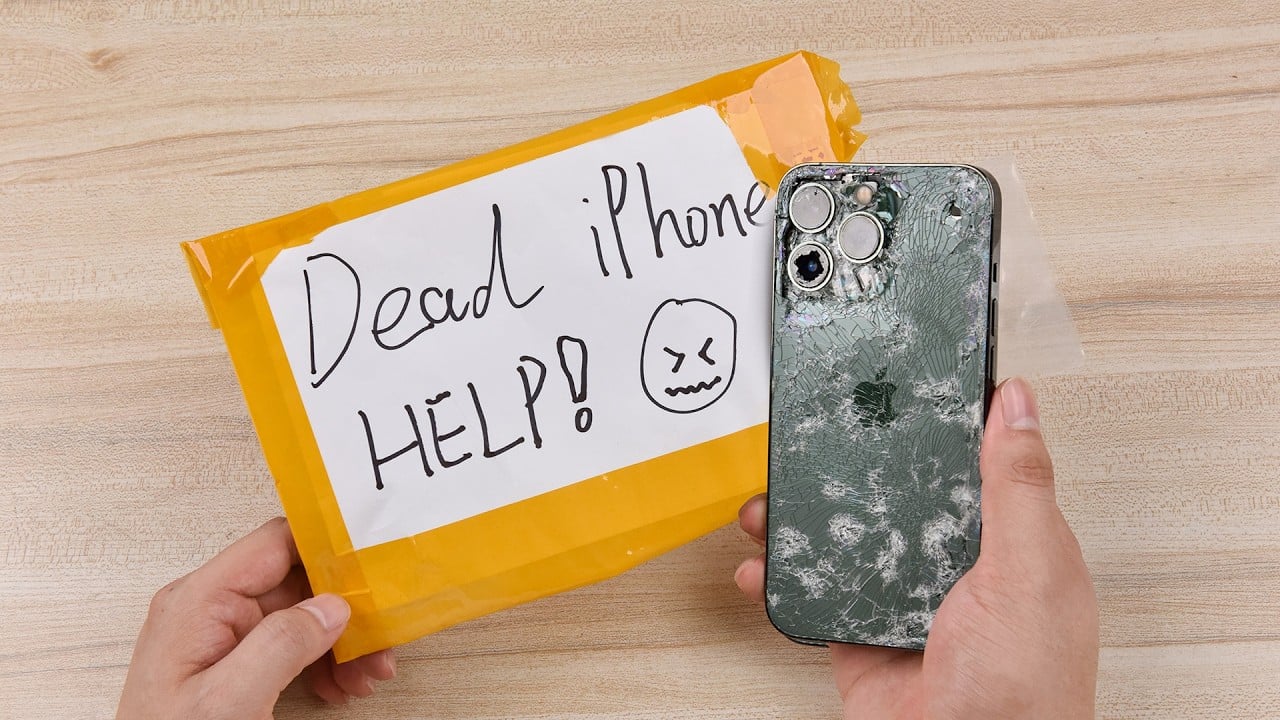
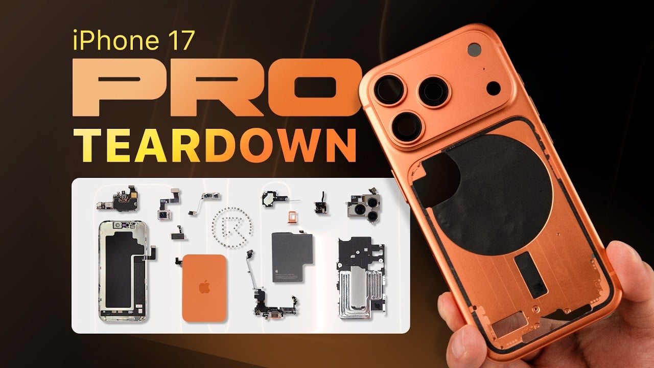
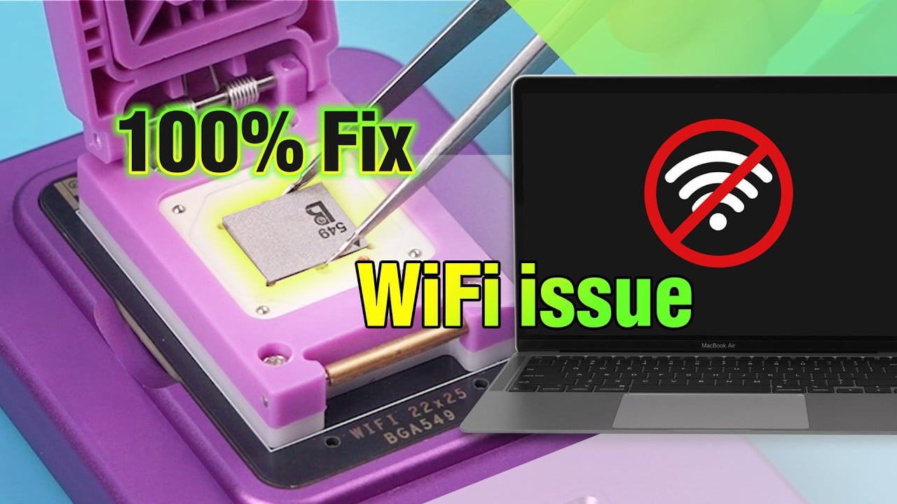
La caméra frontale de l'iPhone ne fonctionne pas ? Par quoi un technicien doit-il commencer ? Suivez notre guide de réparation dès aujourd'hui et apprenez à résoudre les problèmes étape par étape. De plus, REWA LAB vous montrera comment éviter d'endommager davantage la carte logique en adoptant une nouvelle solution de réparation. Découvrez-le dès maintenant !
Test
Effectuer un contrôle cosmétique de la carte logique. La carte logique n'est ni déformée ni endommagée par l'eau. Maintenant, installons la carte logique et les caméras. Obtenez le Assemblage de l'écran de l'iPhone installé et la batterie connectée.
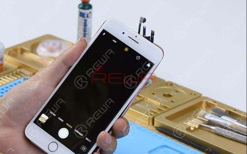
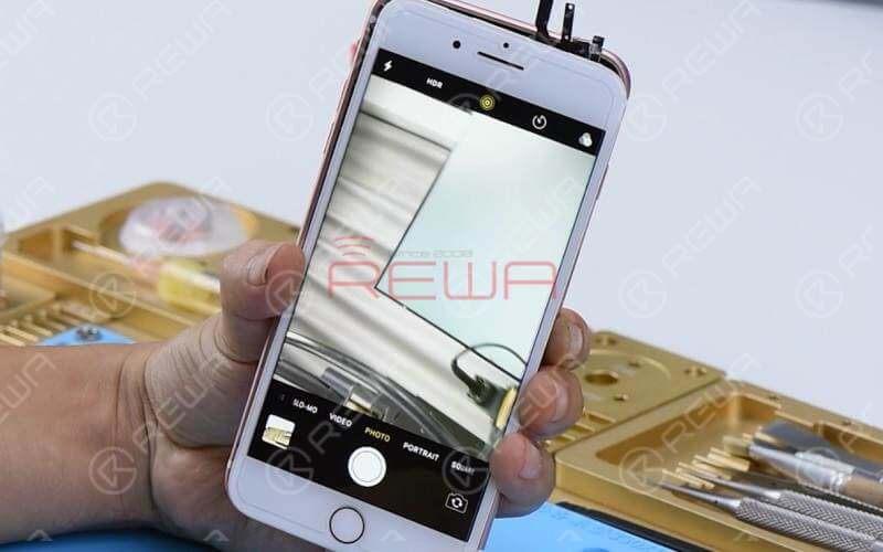
Appuyez sur le bouton d'alimentation pour allumer l'appareil. Appuyez sur l'icône ‘Appareil photo’ et entrez dans le mode appareil photo. La caméra arrière fonctionne normalement. Passez à la caméra avant. Elle ne peut pas être activée.
Diagnostic
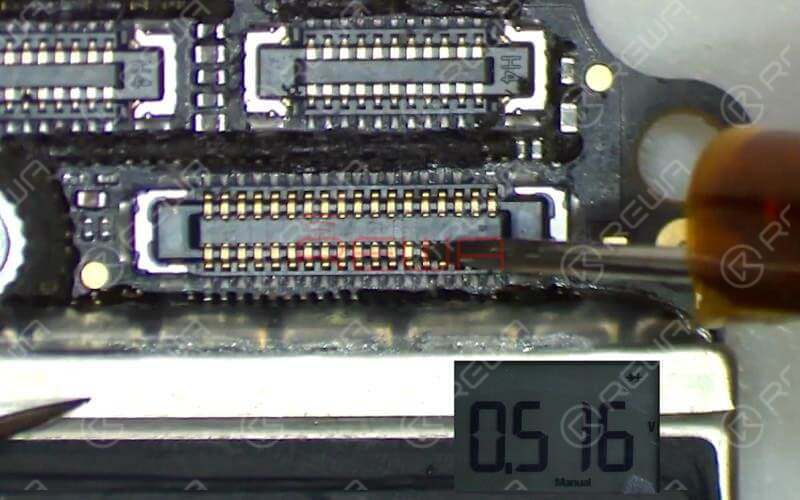
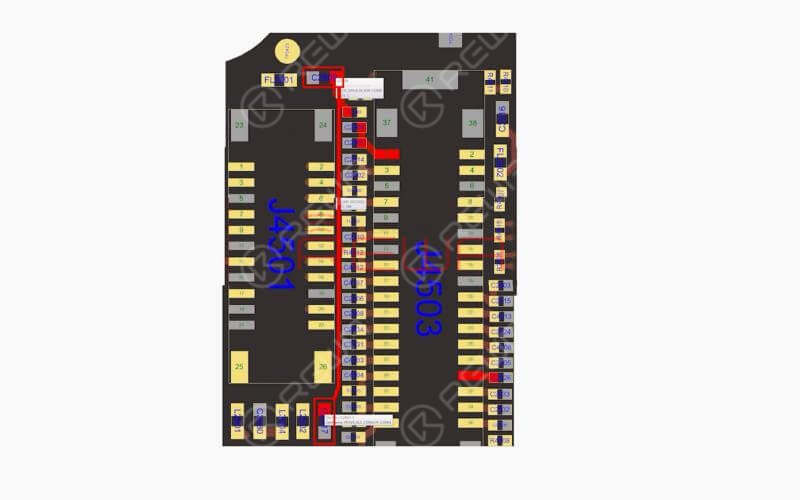
Commençons par vérifier le connecteur J4503 de la caméra frontale et les circuits concernés. Effectuez une mesure en mode diode des broches du connecteur J4503. La valeur mesurée est normale. (Pour cette étape, vous avez besoin d'un logiciel bitmap qui fournit des schémas et des fichiers de carte fiables pour la réparation de la carte mère. REWA utilisé Refox dans la vidéo).
Ensuite, nous devons mesurer la tension de fonctionnement de la caméra frontale. Connecter la carte logique à l'assemblage de l'écran. Connectez le connecteur de la batterie au bloc d'alimentation. Appuyez sur le bouton ON/OFF du bloc d'alimentation pour alimenter la carte logique. Appuyez ensuite sur le bouton d'alimentation de l'unité d'alimentation. Le système détecte alors l'appui sur le bouton d'alimentation.
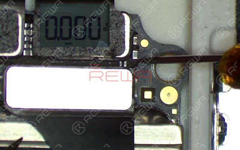
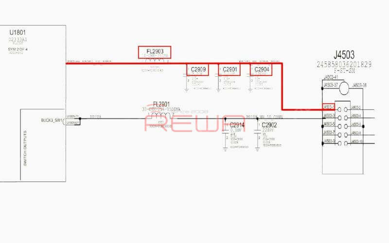
Appuyez sur l'icône ‘Caméra’ pour passer en mode caméra. Effectuez une mesure en mode tension des points de test FL2901 et C2909 de l'alimentation de la caméra frontale. La valeur mesurée sur FL2901 est normale. Aucune tension n'est mesurée sur C2909, ce qui est anormal. La tension normale doit être de 2,9 V. Produite par la broche G10 de U1801, la tension de 2,9 V atteint la broche 1 de J4503 par l'intermédiaire de FL2903, C2909, C2904 et C2901.
Poursuivre la mesure en mode diode de FL2903. D'après la valeur mesurée, FL2903 est dans un état normal. Nous pouvons maintenant confirmer que le défaut est lié à U1801.
Dépannage
Nous pouvons y remédier en remplaçant l'U1801 par un nouveau ou en empruntant une tension de 3V à d'autres points de la carte. Comme l'U1801 est situé à l'arrière du CPU et que le processus de remplacement peut provoquer une pseudo-soudure du CPU, nous adopterons ici la méthode de l'emprunt de tension.
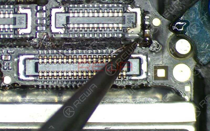
Pour ce faire, nous avons besoin d'un fil émaillé étamé de 0,1 mm. Avec une extrémité du fil soudée à C2917, un point de tension de 3V à proximité, soudez l'autre extrémité à C2909.
Une fois que c'est fait, nettoyez avec le PCB Cleaner. Appliquez un masque de soudure durcissable aux UV sur la zone soudée. Ensuite, solidifiez la carte logique sous une lampe de séchage UV pendant 5 minutes.
Remontage et test
Ensuite, nous pouvons assembler le téléphone et le tester. Appuyez sur l'icône ‘Appareil photo’ pour passer en mode appareil photo. La caméra avant fonctionne normalement. Passez à la caméra arrière. La caméra arrière fonctionne normalement. L'erreur est corrigée.
Outils et pièces nécessaires
- Réparation de la carte mère Support de PCB
- Pistolet à air chaud Station de reprise
- Plate-forme intégrée de réparation de téléphones mobiles
- Alimentation iPower Max Kits d'outils pour le démontage de l'iPhone
Vous pouvez également visiter Chaîne YouTube de REWA pour regarder notre vidéo et apprendre à réparer la caméra frontale de l'iPhone en toute sécurité.
