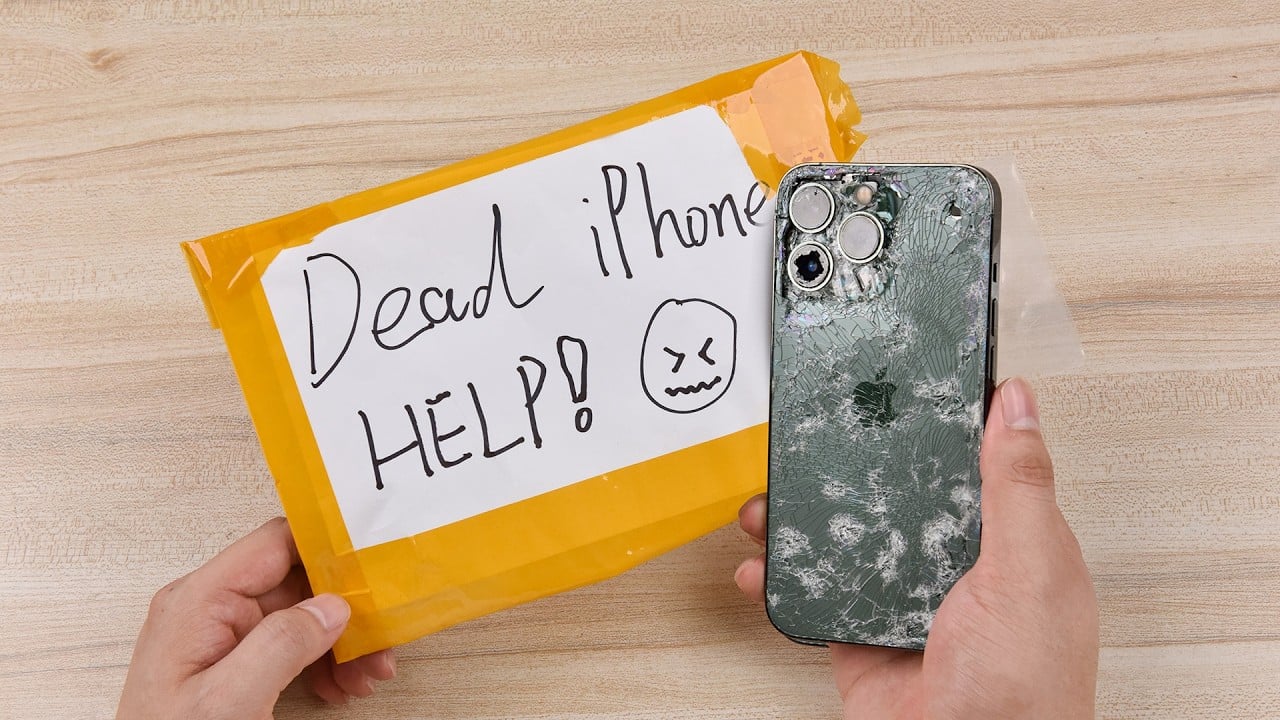
Discovering that your smartphone refuses to power on is the ultimate fear of any device owner. It’s a dreadful experience to encounter a blank screen devoid of any signs of life. In this instance, REWA LAB has a repair case to offer, focusing on resolving the issue of an unresponsive iPhone X.
Step 1: Power up the motherboard for testing
To start, establish the connection between the motherboard and the power supply. If the DC POWER SUPPLY exhibits a higher current reading than usual without initiating the boot-up process, it indicates a short circuit in the motherboard’s main power supply line.

Step 2: Run diode mode measurement
Run diode mode measurement of the J3200 pin 1. The diode value is 408, which means the main power supply line PP_BATT_VCC is normal.

Then measure the J5700 pin 35. The diode value is 0, which means the main power supply line PP_VDD_MAIN is short-circuited.

Since the PP_VDD_MAIN line simultaneously supplies power for the logic board and signal board, we need to separate the motherboard to identify the fault location.
Step 3: Motherboard separation
Cut through the shielding paper with a sculpture knife and put the motherboard on the Heating Platform.

To make it easier to remove the logic board after separation, drive a screw on the logic board.

Set the temperature to 170℃. When the temperature reaches 170℃, use tweezers to remove the logic and signal board.

Step 4: Run diode mode measurement again
Run diode mode measurement of the J5700 pin 35 on the logic board. The diode value is 0. It indicates that the main power supply line PP_VDD_MAIN of the logic board is short-circuited.

Measure the S73 pin of the signal board. The diode value is 306, which means the signal board is normal.

Through the diode mode measurement, it can be confirmed that the fault is on the logic board.
Step 5: Locate and clear the fault
Remove the thermal grease on the logic board.

Then we can locate the faulty component with rosin detecting. Smoke some rosin with the Soldering Iron at 365℃.

Apply a 3V0 voltage to the S74 pin of the logic board. We can see that the rosin on C2990 has melted. It can be confirmed that C2990 has been damaged and needs to be removed.


Attach the logic board to the PCB Holder. Then remove C2990 with QUICK 990 AD Hot Air Gun at 360℃ and airflow 3.

Measure the logic board again after it has cooled. The diode value returns to a normal value of 346. The fault is cleared.

Step 6: Motherboard restoration
Smear rosin with Soldering Iron and solder-wick. Remove the tin on the bonding pad of the logic board and signal board separately.

Clean the motherboard with PCB Cleaner. Remove excess thermal grease on the signal board with a sculpture knife.

Attach the signal board to the Reballing Platform and place the Reballing Stencil in position. Apply a layer of low-temperature Solder Paste evenly.

After reballing, put the signal board on the Heating Platform at 170℃. When the solder ball is formed, turn off the power and cool the signal board.

Apply a small amount of Paste Flux. Align the logic board with the signal board and put it on the Heating Platform at 170 ℃.

When the temperature has risen to 170℃, continue heating for another minute. Install the motherboard on the phone after cooling it for 5 minutes.
Step 7: Boot up and test
Boot up and test. The phone turns on normally and the fault is eliminated.

Conclusion
The iPhone X fails to power on and the motherboard experiences excessive current flow without initiating boot-up. By utilizing a multimeter to assess the primary power supply line on the motherboard, it was determined that the PP_VDD_MAIN line has a short circuit. After isolating the motherboard and conducting a subsequent measurement, we confirmed that the issue resides within the logic board. Through the use of rosin detection, we identified that C2990 had sustained damage. Removing C2990 resolved the problem.
For further repair content, please visit REWA academy website or explore our online shop for repair tools and parts. Also, subscribe to our YouTube channel to access additional phone repair information and techniques.